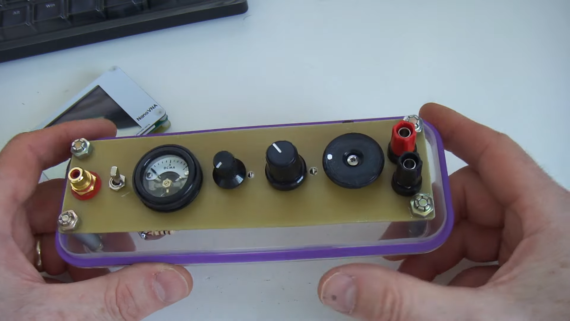
Attaching a 3.2kΩ resistor to the output, an input match of 1:1 SWR can be obtained from 6.5MHz to 30MHz. The second hand box had a few holes in it, so I made this sticker to cover them up! Using this Air Inductance Calculator, I worked out that a 19mm diameter, 52mm long, 16 turn inductor should give an inductance of 1.5uH, so this is what I built. This way, I can build it with a 16 turn secondary, and at the inductance I wanted by altering the diameter and/or length of the coil. So, I decided to use an air wound transformer. I could have made it 16 turns and a 2 turn primary, but then the inductance would be too large for 30MHz. As I wanted a 1:8 turns ratio (for a 1:64 impedance ratio), I needed a primary of 1.33 turns, which was going to be impossible. I looked at using a T200-6 iron powder toroid, but the problem was 1.5μH required only 12 turns. Impedance transformation is calculated by squaring the secondary turns ratio (note ratio, not actual turns) 8² is 64. I wanted to transform 50Ω to around 3000Ω. So, lets build the secondary transformer inductor first. A switch could be added to add a further capacitance of 150-200pf to include 7MHz operation. Sounds perfect to me! If you have a smaller value capacitor, for example 200pf maximum, it should still cover 10MHZ to 30MHz. I would like to cover 7 to 30MHz with my coupler if possibe, so the next thing I needed to design was an inductor that would resonate in a parallel LC circuit at just above 30MHz when the capacitor is at minimum. Using this Resonant LC Calculator, I worked out that an inductance of 1.5μH will resonate at about 33MHz when the capacitor is at 15pf and 6.9MHz when the capacitor is at its maximum of 353pf. I had a capacitor that I wanted to use, which is a Johnson 154-2 air variable capacitor, with a range of 15-353pf. Notice how the feedpoint is not quite as high impedance as the top of the antenna.įirst off, construction will be a juggle between available components and the desired band coverage. Steve has done a lot of research with end fed half waves and I recommend having a read of his pages.īelow is the schematic of the final build.Ĭurrent along the half wave. In practice, I have found Steve AA5TB‘s recommendation of at least 0.05 wavelengths to be accurate. I included a switch to be able to use either.
#Homemade antenna tuner portable#
A very small counterpoise should be adequate from 7 to 30MHz, or you can even use the coax and transceiver as the counterpoise for an even simpler portable set-up. The high impedance means that the feedpoint has a very high voltage but low current, therefore very little ground is required. The problem with end feeding a half wave is also its advantage. A ‘Windom’ type off centre fed dipole (fed 38% along its length) provides around a 200Ω feed. The feed impedance at the very end of a half wave is thousands of ohms, usually somewhere between 2000Ω to 5000Ω, which we need to match to our 50Ω transceiver. This article will explain my findings and reasons for constructing it the way I did.Ī dipole can be fed anywhere along its length. I have been experimenting with feeding end fed half wave antennas matched by a parallel tuned circuit coupler. A ground mounted half wave vertical has a peak radiation angle of 20°, so it makes a good choice for DX. A vertical, a sloper, a piece of wire hung in a hedge are all good examples.


#Homemade antenna tuner how to#
Being able to feed the dipole from one end gives you more options on how to erect an antenna and makes portable operation easier. Sometimes however, the centre feed is not ideal, for example when you want to use it as a vertical. The finished End Fed Half Wave antenna coupler.Ĭentre fed half wave dipoles make great, simple and effective antennas for the HF bands.


 0 kommentar(er)
